
Categories
Tags
-
#Design Of Column Load Cell,single point load cell
#double shear beam load cell,load cell manufacturer
#bending beam load cell,weighbridge load cell
#scale sensor,shear beam load cell
#load cell manufacturer,ball type load cell
#weighing transducer,bending beam load cell
#column load cell
#weighing transducer,single point load cell
#ball type load cell
#double shear beam load cell
#shear beam load cell,ball type load cell
#weighbridge load cell,bending beam load cell
#single point load cell,column load cell
#shear beam load cell,scale sensor
#double shear beam load cell,ball type load cell
#column load cell,weighing transducer
#shear beam load cells
#although they may look similar at first glance
#they work slightly differently
#single point load cell weighing transducer
#Load Cell
Archives
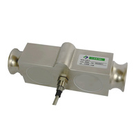
Check the weighing transducer element for dents, deformation, c
-
The following is a step-by-step test in order. If a test fails, the weighing transducer has been damaged and no subsequent tests need to be performed.
Body checkup
Check the weighing transducer cable for obvious signs of damage. Any cuts, crimps, excessive aberrations, or bare wires indicate damage.
Check the weighing transducer element for dents, deformation, cracks, metal corrugation, corrosion, and obvious wear in the load area. The load cell contains sensitive components, and any vibration caused by a drop or impact may damage the internal electronic equipment.
Visually check the flatness (for single-point and double-ended load cells). Use straightedge and flashlight technology for proper visual inspection. Make sure that there are no traces of bending or bending on the load cell. Even a small deflection will adversely affect the load cell.
Electrical inspection
Check zero balance. Place a weighing transducer that is not connected to a load. Connect the input to a stable low-noise power supply. Use a multimeter to measure the output voltage in mV, and then divide it by the input voltage in V to get mV/V. Please refer to the calibration certificate of the load cell to see if this mV/V value is within the tolerance range of the load cell specification.
(Optional) Check for zero return. Like the previous steps, connect the load cell to a stable power source and measure the mV/V output. Make sure it is within the allowable tolerance range. Load the load cell between 50% and 100% of its capacity for 5 seconds. Remove the load and check if the mV/V output returns to the allowable tolerance.
Check insulation. Use a multimeter to check the insulation of the wire with the metal body of the load cell. If the resistance is lower than 2 GigaΩ, the insulation is poor. Ideally, the insulation resistance should be greater than 5 GigaΩ.
Use a multimeter to check the input and output resistance (resistance accuracy of 0.025Ω or higher) to ensure that it is within the allowable error range of the product. See calibration certificate. A difference greater than 0.1Ω indicates that the load sensor is defective.
Check the resistance of the strain gauge one by one. Refer to the figure below to test the resistance. These figures are just examples.
Check input and output resistance. If these values are greater than 3kΩ, it means that the weighing transducer is not good, and it may be caused by a surge or lightning. Check whether the resistance on the calibration table is correct.